A tomographic examination, not one number
Scheimpflug tomography reconstructs anterior-segment geometry from multiple images. The resulting displays include anterior and posterior corneal surfaces, pachymetry, curvature-derived maps, and composite indices. These outputs are related, but they are not interchangeable.
Read the named display and field
A value should be interpreted from its labeled source display, eye, examination, and surface. K1, K2, Km, Kmax, thinnest pachymetry, posterior elevation, and composite indices describe different properties. Copying a visually similar number from another panel can create a clinically important source error.
How CER-AI reads Pentacam images
CER-AI first identifies the complete five-image source set and laterality. Its image-extraction layer transcribes only explicitly labeled values from each field's registered display region. It does not sample map colors, estimate an unreadable number, or calculate one locked field from another. Each accepted value carries its source identifier into reconciliation, assessment, and reporting.
What happens when a value is uncertain
An absent, obscured, wrong-screen, or conflicting locked value remains null. CER-AI may perform a field-specific targeted reread; if the canonical box still cannot be resolved, it requests surgeon entry or confirmation when that workflow permits. It does not choose the first, average, minimum, maximum, or most concerning value to hide disagreement.
Quality precedes interpretation
Acquisition quality, fixation, blinking, tear-film disturbance, decentration, and contact-lens effects can alter measurements. A quality warning does not automatically define the clinical result; it signals that the examination and the affected values require review or repeat acquisition when appropriate.
Compare patterns across channels
Curvature describes optical shape, elevation describes surface position relative to a reference surface, and pachymetric progression describes spatial thickness behavior. Concordant abnormal findings are different from an isolated borderline value. Bilateral comparison and prior examinations can add context but do not replace inspection of each eye.
From concepts to structured assessment
Connect this educational module to the physician-focused CER-AI corneal ectasia risk assessment overview. Corneal topography and tomography are distinct evidence channels within the broader preoperative ectasia screening workflow.
Five-image synthetic Pentacam source example
This set demonstrates how one suspicious teaching eye (OD) and one normal teaching eye (OS) align across the five mandatory source screens. Select an image to open it at full size.
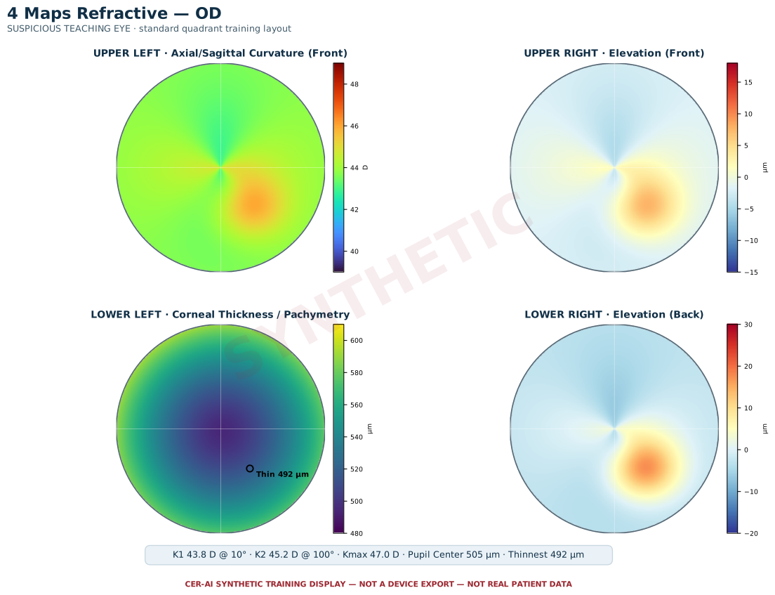
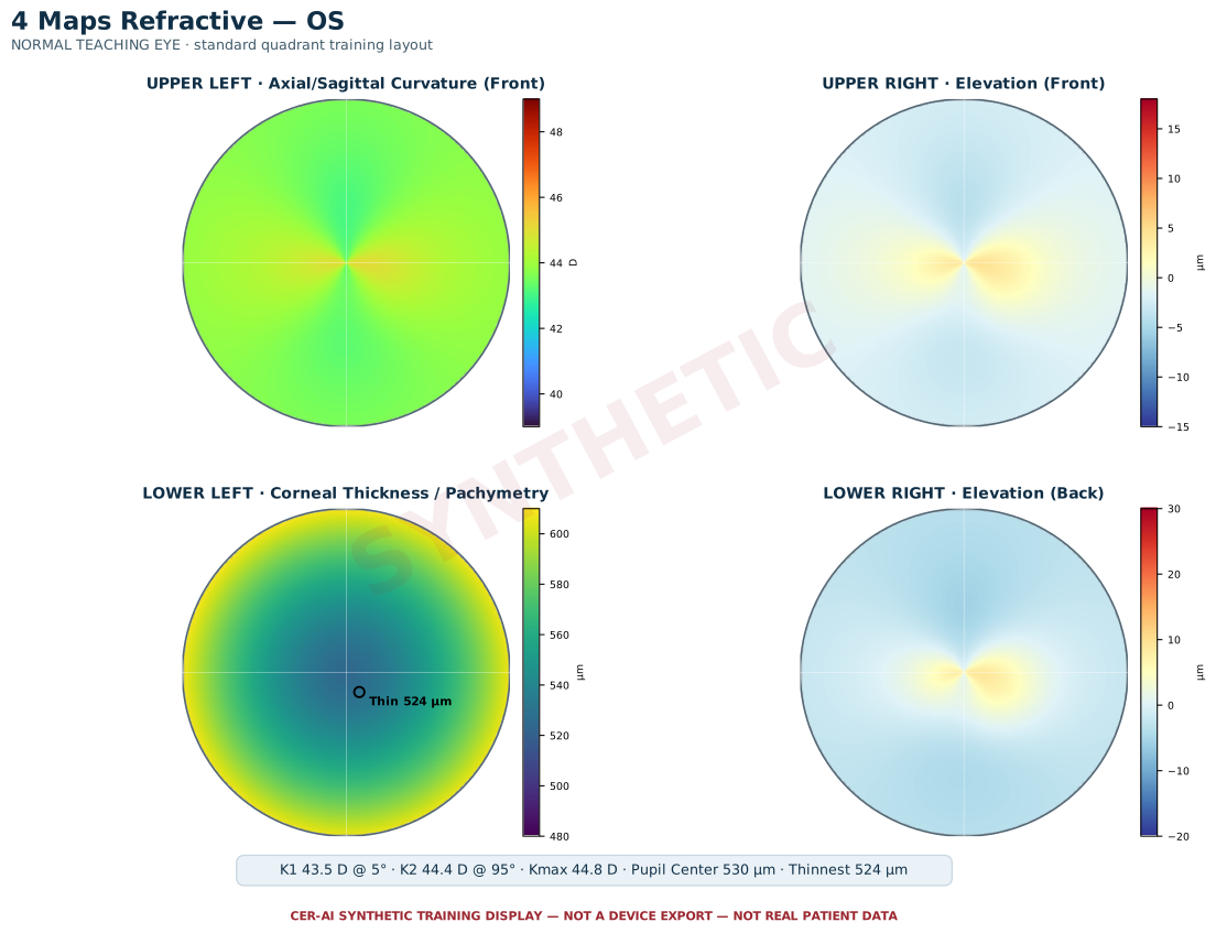
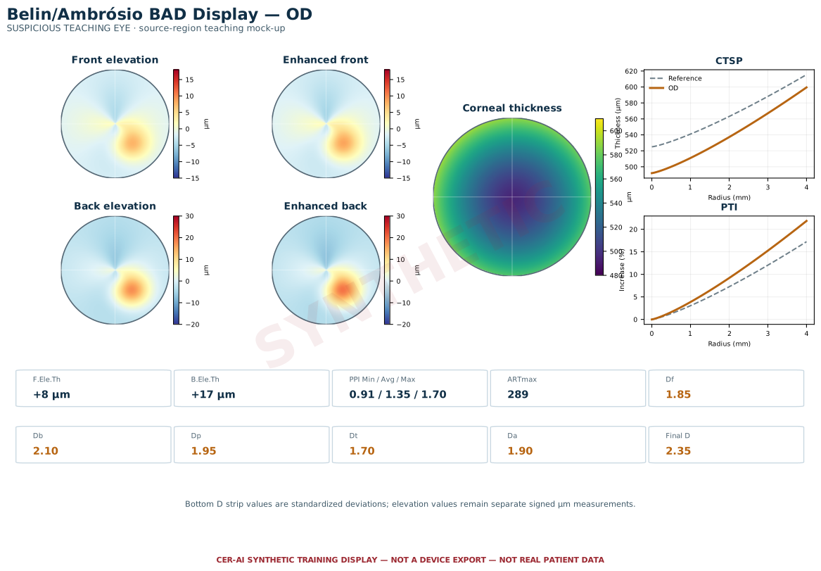
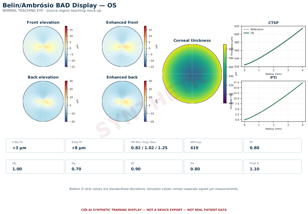
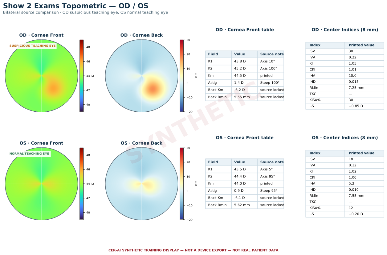
Important: These figures are not real Pentacam device exports or real patient data. They teach screen family, laterality, source fields, and standard layout only; they must not be used for diagnosis, treatment decisions, or as CER-AI patient inputs.
Surgeon upload and source confirmation
| Required image | Surgeon must define/confirm | Image acquisition requirement |
|---|---|---|
| 1. 4 Maps Refractive — OD | Right eye; 4 Maps Refractive | Full display, captured directly from the front |
| 2. 4 Maps Refractive — OS | Left eye; 4 Maps Refractive | Full display, captured directly from the front |
| 3. Belin/Ambrósio BAD Display — OD | Right eye; BAD Display | Full display with bottom D strip and labeled boxes visible |
| 4. Belin/Ambrósio BAD Display — OS | Left eye; BAD Display | Full display with bottom D strip and labeled boxes visible |
| 5. Show 2 Exams Topometric | Bilateral comparison; OD and OS panels identified | Full display with Cornea Front, Cornea Back, and center indices readable |
The surgeon must upload and confirm all five Pentacam source images. Use a clear screenshot or a photograph taken perpendicular to the screen—not from an angle. Avoid blur, glare, perspective distortion, compression, cropping, shadows, and covered labels. Poor image quality can make a field unreadable or inconsistent; CER-AI must request a clearer source rather than infer a value. Clear acquisition supports consistency but does not guarantee clinical correctness.
Standard 4 Maps Refractive quadrant localization
| Screen location | Required printed map type | CER-AI use and conflict rule |
|---|---|---|
| Upper left | Axial/Sagittal Curvature (Front) | Only this anterior/front curvature map is used by the deterministic SRAX geometry layer. |
| Upper right | Elevation (Front) | Anterior elevation pattern review; it does not substitute for the BAD Display F.Ele.Th labeled value. |
| Lower left | Corneal Thickness / Pachymetry | Spatial thickness-pattern review; decision fields still come from their explicitly labeled Pupil Center and Thinnest Location values. |
| Lower right | Elevation (Back) | Posterior elevation pattern review; it does not substitute for BAD Display B.Ele.Th or Show 2 Cornea Back values. |
CER-AI requires the standard full 4 Maps Refractive layout and verifies the printed map label as well as its quadrant. Do not upload a custom/rearranged four-map layout or place an anterior sagittal-curvature map in a right-hand quadrant. A label–position mismatch, front/back substitution, rotation, or crop is a source conflict and must be corrected with a standard export or clear front-on image.
Required Pentacam source set
| Source image | Required set | CER-AI extraction role |
|---|---|---|
| 4 Maps Refractive | One OD and one OS | Pupil Center pachymetry, circle-marked Thinnest Location, K Max (Front), HWTW, acquisition/identity evidence, and deterministic SRAX geometry. |
| Belin/Ambrósio BAD Display | One OD and one OS | Signed F.Ele.Th and B.Ele.Th; PPI Min/Avg/Max and ARTmax; Df/Db/Dp/Dt/Da and Final D; the specific upper-middle Axis field is retained for its validation role. BAD K1/K2 are not required for ML7. |
| Show 2 Exams Topometric | One bilateral comparison page | For each eye: Cornea Front K1/K2/axes/Km/Astig; Cornea Back Km and Rmin; center 8-mm indices including ISV, IVA, KI, CKI, IHA, IHD, RMin, KISA, and signed I-S. |
| Excimer treatment card | Optional sixth image | Only the labeled Düzeltme Miktarı row may supply treatment correction. If absent, the surgeon provides complete manifest and intended refraction for both eyes. |
All five Pentacam pages must be identified before targeted rereading, geometric SRAX analysis, clinical scoring, or report generation. A duplicate page never substitutes for a missing source family.
Source-locked field map
| Registered region | Accepted fields | Prohibited substitution |
|---|---|---|
| Show 2 → Cornea Front | K1, K1 axis, K2, K2 axis, printed Km, Astig and steep axis | No Cornea Back, Kmax, True Net Power, map spot, or calculated mean |
| Show 2 → Cornea Back | Printed posterior Km and posterior Rmin | No Cornea Front Rmin or center topometric RMin |
| Show 2 → center Indices (8 mm) | ISV, IVA, KI, CKI, IHA, IHD, topometric RMin, KISA, signed I-S | No index may substitute for I-S; preserve the printed sign |
| 4 Maps → lower-left labeled box | Pupil Center pachymetry, Thinnest Location pachymetry, K Max (Front), HWTW | No Pachy Vertex, map color/spot, or neighboring number |
| BAD → elevation row | Signed F.Ele.Th and B.Ele.Th in µm | No elevation-map spot, K field, or unlabeled value |
| BAD → Progression Index | PPI Min/Avg/Max and ARTmax | No back-calculation of Dp or Da |
| BAD → bottom D strip | Df, Db, Dp, Dt, Da, Final D | No reconstruction of any component or Final D |
The registry distinguishes fields that look similar. In particular, posterior Rmin and center topometric RMin are separate measurements. ML7 planning reuses the existing canonical Cornea Front K1/K2; it does not request a second pair.
From image to auditable report
| Stage | What CER-AI does | Safety behavior |
|---|---|---|
| 1. Page identity | Confirms screen family, OD/OS laterality, patient/exam identity, and the five-source set | Assessment does not start when a mandatory source is missing or unidentified |
| 2. Primary transcription | Reads labeled numeric boxes and records exact canonical source IDs | Wrong-screen or inferred values are rejected |
| 3. Reconciliation | Merges readings only when field, eye, and source agree | Same-source disagreement clears the field; it is never averaged |
| 4. Targeted reread | Re-examines the exact missing or unreadable box | The prompt remains field- and source-specific |
| 5. Surgeon completion | Accepts an explicit surgeon-entered or confirmed value where permitted | Surgeon input is authoritative and labeled SURGEON_CONFIRMED |
| 6. Clinical adapter/report | Maps resolved values into ERSS, BAD-D, NICE, PS3, safety, then copies computed results and provenance into the report | The PDF/Word renderer does not rescore the case |
The image model transcribes dates and printed values; deterministic code calculates age, refraction normalization, SRAX geometry, scores, safety formulas, and final disposition.
Selected sources
- OCULUS Pentacam Interpretation Guide 2024
- Ambrósio et al., JCRS 2006
- Toprak et al., Turkish Journal of Ophthalmology 2023
See the complete CER-AI medical reference registry for broader context.